


s5.07.02 - entities, attributes, keys and entity relationship modelling
Master relational database entities, attributes, primary, foreign, and composite keys for robust relational schema design.

Every app, every website, every digital service you use relies on a perfectly structured database to manage its information. Think about Instagram connecting millions of users to billions of posts, or an airline linking passengers to flights and bookings - it's a seamless dance of data! Today, you're stepping into the shoes of a Data Architect and a Database Administrator. You'll learn the formal grammar for designing these digital blueprints: understanding entities, attributes, and the critical keys that enforce data integrity. Then, you'll master Entity-Relationship Diagrams (ERDs) using industry-standard Crow's Foot notation to visually map out these complex data relationships. Get ready to build robust data foundations!
Learning Outcomes
Factual (Knowing that)
Conceptual (Knowing why)
Procedural (Knowing how)
Recall the precise technical definitions of entity, attribute, primary key, candidate key, secondary key, composite key, and foreign key.
Describe the common types of cardinality using Crow's Foot notation: one-to-one, one-to-many, and many-to-many.
State the role of referential integrity in relational database architectures.
Conceptual (Knowing why)
Analyse why candidate keys must satisfy uniqueness and non-null constraints to qualify as potential primary keys.
Explain how many-to-many relationships are resolved into two one-to-many relationships using an associative entity.
Evaluate the systemic implications of violating referential integrity when modifying or deleting referenced primary key attributes.
Procedural (Knowing how)
Apply Crow's Foot notation to define entities, explicitly listing attributes, underlining primary keys, and designating foreign keys within entity rectangles.
Draw a complete Entity-Relationship Diagram (ERD) using Crow's Foot notation to represent a multi-entity business problem, including the resolution of many-to-many relationships.
Create a normalised relational blueprint for a real-world scenario, establishing valid primary and foreign key associations to ensure data integrity.
The Deep Dive
Relational Blueprints: Entities, Keys, and Crow's Foot ER Modelling
Introduction: The Architecture of Information
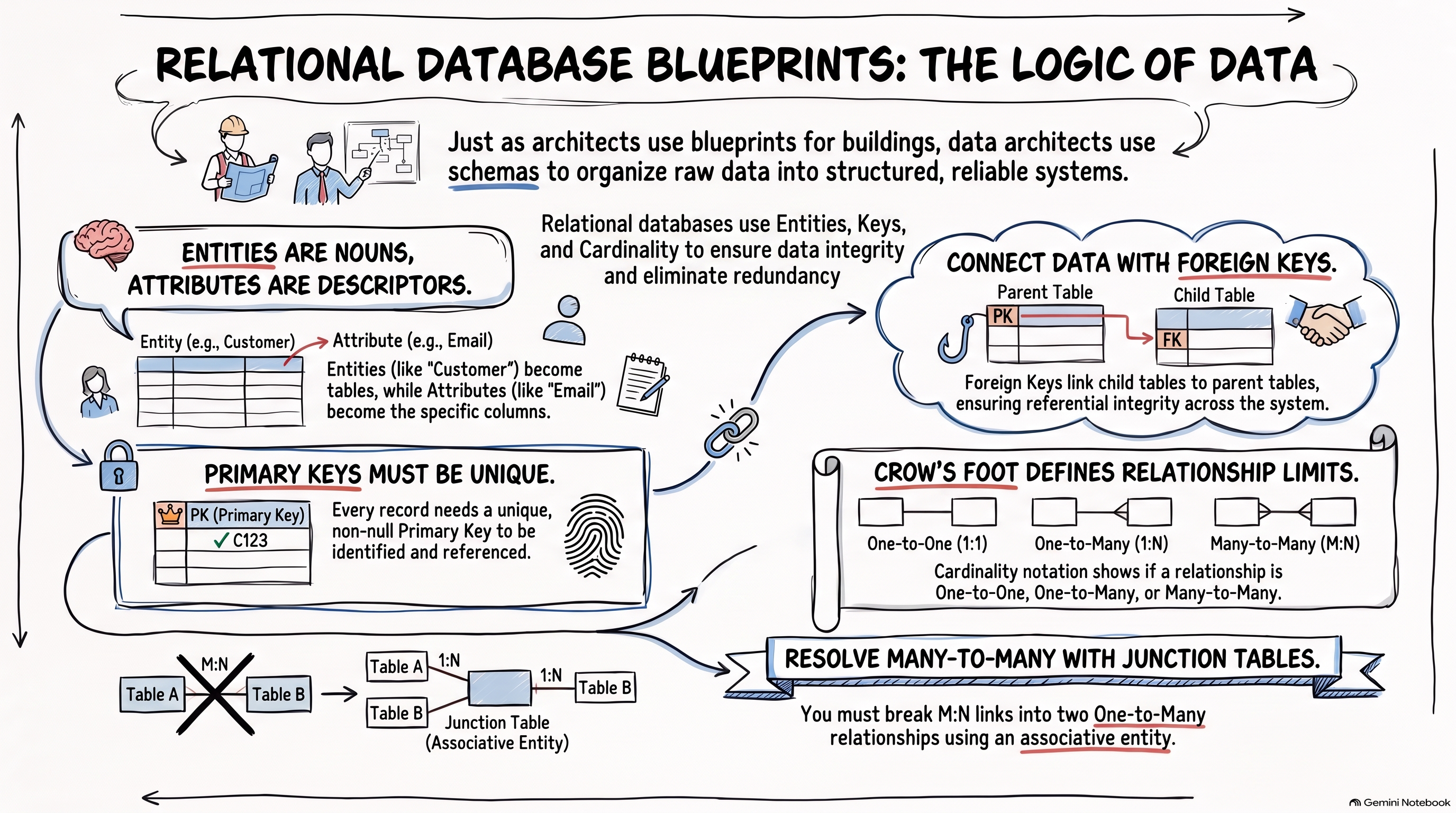
In modern computing, data is the new oil. But raw, unstructured data is often totally useless. Just as a physical architect designs a building, a Data Architect designs a database, creating a formal blueprint called a schema. This schema defines how data is organised, stored, and related, mitigating the issues of data redundancy and inconsistencies that plague simpler flat file systems. This lesson introduces the fundamental grammar and visual language for crafting these essential blueprints.
Entities and Attributes: The Core Components
Entities: The Nouns of Your Data
An entity is a distinct, real-world person, place, object, event, or concept about which an organisation collects and maintains data. Each entity will ultimately correspond to a distinct table (or relation) in your database.
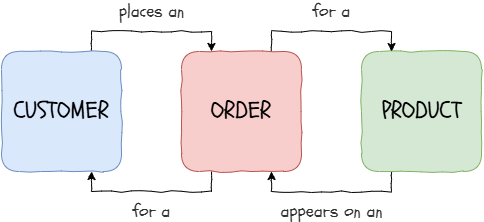
In an e-commerce system, Customer, Product, and Order are all entities and are related by verbs.
Attributes: The Descriptors
An attribute is a specific characteristic, property, or detail that describes an entity. When an entity becomes a table, each attribute becomes a distinct column (or field) with a defined data type (e.g., Integer, Varchar, Date, Boolean). In Crow's Foot ER diagrams, attributes are listed within the entity rectangle.
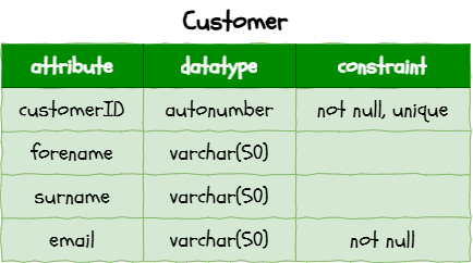
For a customer entity, attributes might include 'customerID', 'forename', 'surname', and 'email'.
The Hierarchy of Relational Keys
Keys are structural constraints applied to attributes that govern record identification, preserve indexing efficiency, and guarantee mathematical consistency across relations.
1
Candidate Keys and the Primary Key
A candidate key is any attribute, or set of attributes, capable of uniquely identifying an individual record within an entity. An entity can have multiple candidate keys. Example: For an
EmployeeFrom these, one candidate key is selected as the Primary Key (PK). A primary key is absolutely critical and must adhere to two fundamental constraints:
1
Uniqueness Constraint: Every record must have a distinct primary key value. Duplicates are strictly forbidden.
2
Entity Integrity Constraint: A primary key cannot contain a null value (PK ≠ ∅). An unknown identifier means the record cannot be reliably located or referenced.
2
Secondary (Alternate) Keys
Any candidate key that was not chosen as the primary key becomes a secondary key (also known as an alternate key). These are often indexed to allow rapid searching and retrieval using alternative unique identifiers without compromising the primary identity of the record. Example: If 'employeeID' is the PK, then 'nationalInsuranceNumber' and 'workEmail' become secondary keys.
3
Composite Primary Keys
Sometimes, no single attribute can guarantee uniqueness. In such cases, two or more attributes are combined to form a composite primary key. This combination, when taken together, uniquely identifies each record. Example: In an
EnrolmentstudentIDmoduleCode4
Foreign Keys and Referential Integrity
A Foreign Key (FK) is an attribute (or collection of attributes) in one entity (the child table) that references the primary key of another entity (the parent table). Foreign keys are the fundamental mechanism that binds separate relations together, forming relationships. Foreign keys enforce referential integrity: a relational rule stipulating that every foreign key value must either match an existing primary key value in the parent relation, or be entirely null. Referential integrity dictates:
You cannot insert a record into the child table with a foreign key value that does not exist as a primary key in the parent table (e.g., creating an
OrdercustomerID: 9999You cannot delete a parent record if dependent foreign key records exist in child tables, unless cascading deletions are explicitly defined (which automatically deletes child records upon parent deletion, requiring careful architectural consideration).
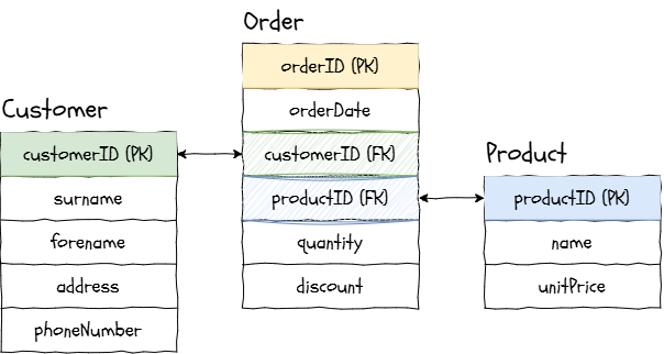
Mapping primary keys and foreign keys ensure referential integrity
Visualising Relationships: Entity-Relationship Diagrams (ERDs)
Entity-Relationship (ER) Modelling is a conceptual data modelling technique used to visually represent the structure of a database. It's the blueprint that helps database designers, developers, and stakeholders understand how entities and their relationships interact.
Crow's Foot Notation (Information Engineering)
For A-Level Computer Science, we focus on Crow's Foot notation (also known as Information Engineering notation) for ERDs. This notation is widely used in industry due to its clarity and unambiguity.
Key Conventions in Crow's Foot ERDs:
Entities: Represented by rectangles. The entity name is at the top, and all attributes are listed below it within the same rectangle on separate lines.
Primary Keys (PK): Underlined within the entity rectangle (e.g., customerID).
Foreign Keys (FK): Marked with an asterisk '*' or '(FK)' next to the attribute name within the entity rectangle (e.g., 'ownerID*').
Relationships: Represented by lines connecting entities. The cardinality symbols (Crow's Feet) are placed at the ends of these lines.
Cardinality: Defining the Links
Cardinality specifies the number of instances of one entity that can be associated with instances of another entity.
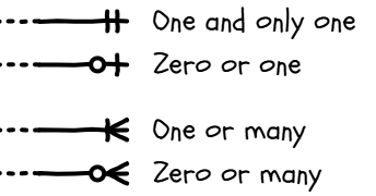
The inner symbol is the minimum and the outer symbol is the maximum
We combine the 'ends' to form a bidirectional relationship between keys.
1
One-to-one (1:1)
Each instance of Entity A is associated with exactly one instance of Entity B, and vice-versa.
Notation: A straight line on both ends, with either a ◯ and a | (for zero or one) or a || for one and only one.
Example: A
PersonPassportPassportPerson
1:1 relationship
2
One-to-Many (1:M)
One instance of Entity A can be associated with many instances of Entity B, but each instance of Entity B is associated with only one instance of Entity A.
Notation: A straight line (one) at one end and a crow's foot (many) at the other.
Example: A
DepartmentEmployeeEmployeeDepartment
1:N relationship
3
Many-to-Many (M:N)
One instance of Entity A can be associated with many instances of Entity B, and vice-versa.
Notation: A crow's foot on both ends.
Example: A
StudentCourseCourseStudent
M:N relationship
CRUCIAL: Resolution for M:N
Relational databases cannot directly implement many-to-many relationships. They must be resolved into two one-to-many relationships through an associative entity (also known as a junction or linking table). This new entity holds the primary keys of both original entities as foreign keys, forming its own composite primary key. It can also hold attributes specific to the relationship itself (e.g., a 'Grade' for an 'Enrolment' associative entity). Generally, the associative entity represents an event.
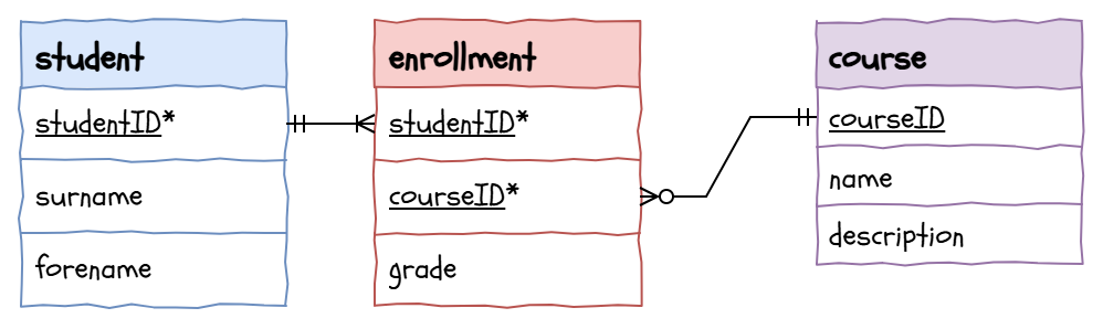
Relational databases cannot directly implement many-to-many relationships. They must be resolved into two one-to-many relationships through an associative entity (also known as a junction or linking table). This new entity holds the primary keys of both original entities as foreign keys, forming its own composite primary key. It can also hold attributes specific to the relationship itself (e.g., a 'Grade' for an 'Enrolment' associative entity). Generally, the associative entity represents an event.
Adding an associative entity to fix the M:N relationship
Take the opposing view. Primary key theory states that a primary key should be entirely immutable and never altered once issued. Construct a robust argument advocating for why a company might be tempted to change an existing primary key (such as updating an employee's badge code or re-formatting national account numbers). Then, write a devastating architectural critique detailing the catastrophic referential integrity failures this update would trigger across legacy systems and linked foreign tables.
Comprehension Questions
Answer these questions on your lesson sheet.1
Distinguish between an entity and an attribute, providing an example of each in a library system context.
2
State the two mandatory rules that any attribute must satisfy to be selected as a primary key, and explain their importance.
3
Explain the operational difference between a candidate key and a secondary key.
4
Describe a specific real-world scenario where a single attribute is insufficient to uniquely identify a record, necessitating a composite primary key.
5
Define referential integrity and explain what occurs if a software system attempts to record an order for a customer who has been deleted from the database without cascading rules.

Task Designing a University Academic Enrolment System
Welcome, data architects! A prestigious university is overhauling its outdated academic administration system. The current system suffers from massive data redundancy, data inconsistencies, and lacks clear data blueprints for managing student enrolments, course structures, and teaching assignments. Your critical mission is to design a unified relational schema using Crow's Foot Entity-Relationship Diagrams (ERDs) that accurately models the university's academic logic.
This challenge requires precision, a deep understanding of key constraints, and the ability to resolve complex relationships. This is a task worthy of a true Software Architect!
0
Get Organised!
Open your web browser and navigate to app.diagrams.net (or use another diagramming tool).
Select Blank Diagram and name your file UniversityEnrolment.
1
Find the shapes you'll need
The table tool
It's easier to use the table tool to create your entities. You'll find it in the 'Misc' panel. The table operations (add/delete row/column) are hidden at the bottom of the right hand properties panel.
The Crow's Feet
There are pre-built crows feet connectors in the 'Entity Relation' panel but honestly, it's easier to fashion them ourselves. You can pull out connectors from any component in a shape by hovering over the edge until you see a green circle then dragging a connector out to a target green circle another shape. If you single click the line, there are options for the start and end shapes where you can choose the correct crow's foot. Sometimes, the connector will be the wrong way around but, instead of choosing new ends, there is a Reverse button in the Arrange panel.
2
Deconstruct the University Scenario
Carefully evaluate the university's business brief:
University Academic System Specification
The university needs a robust system to manage its academic enrolment process.
The university needs a robust system to manage its academic enrolment process.
It tracks Students (StudentID, FirstName, LastName, DateOfBirth, EmailAddress).
Students enrol in specific Degree Programmes (DegreeID, DegreeName, AwardingBody, DurationYears). A degree programme contains many students, but each student is enrolled in exactly one degree programme.
The university offers numerous Modules (ModuleCode, ModuleTitle, Credits, Level).
Lecturers are employed to teach (LecturerID, FirstName, LastName, Department, OfficeNumber). Each lecturer teaches many modules, but each module is taught by only one specific lecturer.
A Student can enrol in many Modules, and each Module can have many Students enrolled in it. The system needs to record the date a student enrolled in a module and their final grade.
3
Entity and Attribute Identification
From the scenario, identify all distinct entities: Student, Degree Programme, Module, and Lecturer. List them on your lesson sheet first.
For each entity, create a structured specification table (or list directly in Diagrams.net within the entity rectangle) detailing:
Attribute Name
Intended Data Type (e.g., INTEGER, VARCHAR(n), DATE)
Field Constraints (e.g., NOT NULL, UNIQUE)
Example: For the
Student4
Key Allocation (Primary, Composite, Foreign)
For each entity, assign an immutable, unique Primary Key. Remember to underline it.
Identify any Composite Primary Keys where a single attribute is insufficient for uniqueness.
Insert appropriate Foreign Keys into dependent entities to establish relationships (e.g., linking a 'Student' to a 'Degree Programme' via 'DegreeID*'). Mark foreign keys with an asterisk '*'.
5
Relationship Mapping and M:N Resolution
Identify all relationships between your entities. Pay close attention to the cardinality (1:1, 1:M, M:N). Draw the cardinality arrows between the primary and foreign keys.
Crucially, you will encounter one Many-to-Many (M:N) relationship:
Between Students and Modules.
For this M:N relationship, create an associative entity (e.g., 'Enrolment'). This new entity should contain the primary keys of both original entities as foreign keys, forming its own composite primary key. Add any attributes unique to that intersection (e.g., 'EnrolmentDate', 'Grade').
6
Construct the Crow's Foot ERD
Using 'app.diagrams.net', draw your complete Entity-Relationship Diagram (ERD).
Ensure strict adherence to Crow's Foot notation:
Entities as rectangles with attributes listed inside (PK underlined, FK marked with `*`).
Relationships as branched lines connecting attributes, with cardinality symbols (crow's feet, single lines, circles) placed at the ends.
Verify that all M:N relationships are correctly resolved with associative entities.

Hungry for more?
Search the web: database normalisation first second third normal form examples
Ask an AI: Click on the carefully written prompt below to learn more...

Role: Senior Database Architect. Task: Explain the architectural trade-offs between using natural keys and synthetic surrogate keys in relational database design. Length: Under 180 words. Audience: A-Level Computer Science student. Tone: Rigorous, academic, and objective. Constraints: Must include a concrete example contrasting National Insurance Number with an Auto-Incrementing Integer ID. NO intro, NO outro, NO deviation from the topic, NO follow-up questions.
Explore Non-Relational Models: Research how document databases (e.g., MongoDB) model data without strict schemas and compare their approach to relationships with the relational model.
Outcome: A comprehensive, formally documented Crow's Foot ERD for the university academic enrolment system, correctly identifying entities, attributes, primary and foreign keys, and resolved many-to-many relationships, saved digitally.

Sticky Note Challenge
Write down a three-line explanation of why a composite primary key is structurally superior to combining two values into a single text string (e.g., keepingstudentIDmoduleCodeST102-CS101
Last modified: October 6th, 2026


